Distortion, Clipping and Operating Point Shift
This is meant to be an original contribution to the repertoire of Valve / Tube distortion circuits. It is not unlikely that this circuit has been described before, but I could find no reference to it on the web.
Similar distortion results can be achieved using junction fets but the crucial non linear characteristics of fets vary by 5:1 within any single type. Bipolar transistors used as voltage amplifiers are among the most reproducible devices in electronics. The circuit as shown works at impedance levels that are incompatible with standard guitar pickups. This problem is easily solved when the stage forms part of an amplifier.
Most of the tube distortion circuits one sees are designed to work at fairly high levels of distortion. No one seems interested in the small amounts of second harmonic that sweeten a guitar sound and add that slight background, barely audible, intermodulation that I as an old fashioned jazz player often like to hear.
The circuit will make a smooth transition from virtually no distortion to tens of percent with no abrupt discontinuity as the level is increased.
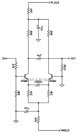
A typical implementation of the circuit is shown in the above diagram. A common emitter stage is coupled to a common base stage by a capacitor. The non linear input impedance of the common base stage interacts with the nonlinear emitter resistance of the common emitter stage to produce an ideal overall transconductance characteristic. The effect is similar to the conventional long tailed pair but, because of the capacitive coupling, the initial bias conditions of both transistors are independently settable. There is no need for matched devices.
In the example shown above, the input is fed through a resistive attenuator. This is to bring the input voltage range into approximate match with that of a valve stage. The overall gain is reduced to 7dB. The signal to noise ratio in a 10kHz bandwidth relative to the 3% distortion level of 250mV at the input is greater than 95dB, which is amply adequate for a guitar amplifier stage.
The maximum peak to peak output current swing for any plausible input is defined by the two emitter tail resistors. The collector load resistor is chosen so that the collector-base voltage never falls to zero. Clipping is defined by the same non-linearities that produce the initial distortion. This results in a smooth and gradual rise in distortion as the input level is increased. The circuit naturally works both clean and distorted.
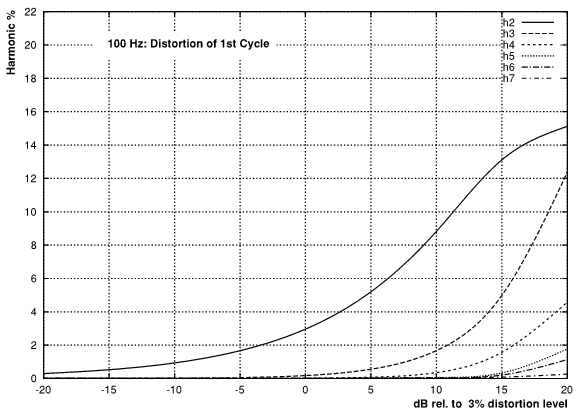
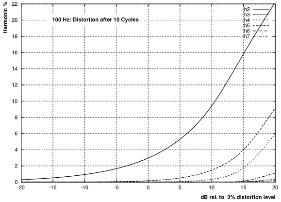
When the two bias currents are unequal, distortion is predominantly second harmonic, with a third harmonic component that rises with level. In addition, the biasing of the stage shifts with level. This means that the harmonic structure of the output varies with time for a constant input. The graphs below show how the harmonics vary with level both immediately and after 10 cycles of 100 Hz.
When the two bias currents are equal, distortion is predominantly odd harmonic (the small amount of even harmonics is caused by the bias resistors not being current sources) and there is no bias shift with level.
© 2004 Arthur M Quinn

This work is licensed under a Creative Commons Attribution 2.0 UK: England
& Wales License.